
1.1 Preamble
The robot can be defined as a machine that, based on a preset programming, can make intelligent decisions and perform tasks with or without close supervision (Adebola 2012). This paper presents details of the robotic arm developed in a final year project at the Obafemi Awolowo University. Please note the project is non-copyrighted.
The robot was developed to be used for educational purposes and to be made from locally available materials. The robotic arm is a five degree of freedom robot with four of its joints (joint at gripper excluded) capable of 360o motion. The robot framework is made of transparent Perspex while the motors used were gotten from a toy car and from old television antennas.
1.2 Basic Mechanics of the Robot
As previously stated, the robot is a five degree of freedom robot. It has four revolute joints and one prismatic joint located at the gripper. Figure 1.1 shows a free body diagram of the robot arm, its links, weights and joints using the Denavit-Hartenberg (DH) Convention as well as an adapted schematic. Upon calculation of torque and kinematics, various results were obtained.


Figure 1.1: A diagram showing the lengths and weights of the experimental robot arm
Torque about Joint 1,
τ1= ((L1W1)/2) + L1W2 + (L1+ (L2/2))W3 + (L1+L2)W4 + (L1+L2+ (L3/2))W5 + (L1+L2+L3)W6 ….(1.1)
Torque about Joint 2,
τ2= ((L2W3)/2) + L2W4 + (L2+ (L3/2))W5 + (L2+L3)W6 ……………………. (1.2)
Torque about Joint 3,
τ3= ((L3W5)/2) + L3W6 ……………………. (1.3)
The location of the central point of the end effector (gripper) of the robotic arm using forward kinematics is given by 1.4 while its jaw positions are given by 1.5.


Equations 1.6, 1.7 and 1.8 together make up the joint configuration of the robotic arm to locate the gripper at a particular point in space.


1.3 Electronics of the Robot
As actuator for each of the joints of the robot, electric motors were stripped from old television antennas and from toys. More about this is said in section 1.5. The key components of the robot’s electronic set-up are:
- Silicon Diodes (1N4000)
- Resistors-4.7kΩ
- Relays
- A Bridge Rectifier
- Transistors
- Industrial controller(IPQ77)
- 12V 3 Anode Transformer
- Capacitors
- Light Dependent Resistors (LDRs) (these form the centre-point for the robot control)
The power supply to the electronic circuit and thus to the entire robot is made up of a 240V 500mA 12 V 3 anode transformer, two 1000μF electrolytic capacitors and a bridge rectifier. This DC voltage is then converted into the AC required by each of the stripped television antenna motors using four 2-Pole 12 Volts relays. Four 5W 100Ω resistors (high wattage) were used to reduce the current flowing into the relays while two 56Ω resistors connected in parallel were used for limiting the current to the gripper. The nucleus of the electronic circuit is made up of three IPQ77 (Each IPQ77 could handle two of the motors), ten TIP41 and five TIP42 (each motor is controlled by two TIP41 and one TIP42). Plate 1.1 shows the completed electronic circuit.
Between the electronic circuit and the computer software interface exists a set-up which eradicates the need for a USB port or serial port set-up. The light dependent resistor (LDR) is a special kind of resistor whose resistance drops appreciably when it is exposed to light. The higher the intensity of light focused on the LDR, the lower its resistance. This resistor was used as a medium of sending instructions from the computer to the robot arm via the electronic circuit. Ten LDRs were mounted on a strip of vero-board and connected via wires to the electronic circuit. Two LDRs each control a robot joint. Apart from the LDRs controlling the gripper, for each set of two LDRs, the lower LDR constantly receives no light(or a zero in binary parlance) while the top LDR when it detects a white light sends a signal into the circuit thus beginning the movement. Once this white light disappears, the signal is cut stopping movement. Plate 1.2 shows the strip of vero-board containing the LDRs.
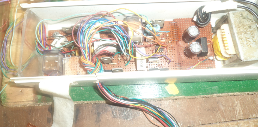
Plate 1.1: A diagram showing the completed electronic circuit.

Plate 1.2: A diagram showing the LDRs assembled on a vero-board
1.4 Computing
The software used to control the robotic arm was written using the Visual Studio C Sharp(C#) platform. The software interface basically consists of a status bar, five control boxes each of which corresponds to an individual motor of the robot and contains buttons for its control, and a black pane at the right end of the screen. The veroboard containing the LDRs is attached to this side of the screen on this black pane. When a button is clicked in any control box, a corresponding white box flashes and this signal is picked up by a particular LDR and goes directly into the electronic circuit as stated above. Appendix A shows the written code. Figure 1.2 shows the interface.

Figure 1.2: A diagram showing the software interface
1.5 Materials Selection
Because this robot was built to be used for educational purposes, it was believed that much was to be gained by having a transparent frame. As such a transparent form of plastic (such as those used in making PET bottles) was considered versus Perspex (known as Poly (methyl 2-methylpropenoate). Aluminium was also considered though it was not transparent. Eventually Perspex was chosen and forms the entire framework of the robot. .
1.6 Cost Reduction and Sustainability
In order to reduce cost, it was necessary to look for local approximate equivalents for electric motors that would otherwise have needed to be imported. DC motors from old television antennas and from children toys were stripped, tested and suitable ones were used. Apart from the gripper joint for which a DC motor from a toy was used, for every other joint DC motors from old television antennas were used. Plate 1.3 shows an array of some of the motors considered for the robotic arm. The second motor is the motor selected for the gripper while the third motor is an example of the television antenna motors chosen for all the other joints.

Plate 1.3: A diagram showing some of the motors considered for the robot arm.
2.1 Educational Applications and Possible Resources
This robot is to be built from scratch by the students. It will be especially challenging for students within the late primary school and secondary school gap. From learning to accurately calculate required torque based on selected dimensions to accurately fitting the motors to the links, cut from Perspex, using thin metal brackets and screws, to soldering electronic components on a vero-board in required order to accurately implementing the provided software and then setting up the entire robotic arm system; students are introduce to mechanics, electronics and a little computing. Also because the robotic arm is to be built using motors sourced locally by themselves, the students are taught from an early age to begin to consider local alternatives to foreign technology. Also as they view the good use to which old parts, that would otherwise have been disposed of, are put, they are subtly introduced to recycling.
3.1 List of Parts
The table 1.1 shows the various components of the robotic arm and its electronic circuit as well as the quantities used. Other details such as where the components could be procured, their availability and of course cost are provided. This cost is given in Naira. As shown, converting the total to Dollars using a conversion rate of 1 Dollar = 158 Naira we have a total cost of 50 Dollars.
Table 1.1: A table showing details concerning the components of the robot.

4. 1 Other Tools and Equipment Used
Tools and equipment needed to construct the robot are shown in table 1.2. Costs are displayed in Naira. As shown, converting the total to Dollars using a conversion rate of 1 Dollar = 158 Naira we have a total cost of 9 Dollars. Datasheets are also needed for both the IPQ77 controllers and the TIP41 and TIP42 transistors.
Table 1.2: A table showing tools and equipment needed to construct the robot and their costs

5.1 Dimensions for the Robot
The dimensions of the robot are as follows:
Thickness of Perspex = 3mm = 0.3 cm
Density of Perspex = 1.20g/cm3
General width of links = 5cm.
Length of link 1, L1= 14cm
Length of link 2, L2 = 12.5cm
Length of link 3, L3 = 11.5cm,
Volume of link 1, V1 = 21cm3,
Volume of link 2, V3= 18.75cm3,
Volume of link 3, V5 = 17.25cm3
6.1 Step-By-Step Instructions for Creating the Robotic Arm
Robotic Arm Frame
- Get a suitable platform preferably of wood upon which both the robot and its electronic circuit will sit.
- Sit the base motor on the platform and use metal brackets and screws to attach it firmly to the platform.
- Cut a square shape of approximately 14 cm by 14 cm out of the Perspex. This will serve as the base.
- Make a hole just big enough to allow the tip of the shaft of the base motor to pass through at the centre of the base. Pass just the tip of the base motor through this hole. Use the soldering iron to make two parallel lines, about 1.5 cm in length with a distance of about 3cm between them, also at the centre of the base. Through these holes, pass a strip of metal bracket. Use screws to attach the ends of the metal bracket to the top of the base motor thus attaching the base to the base motor.
- Choose a side of the centre of the base where it will be ideal to locate the shoulder motor. Again use the soldering iron to make two parallel lines, this time about 1 cm in length with the distance between the, just slightly more than the diameter of the bottom of the shoulder motor. Place the shoulder motor on its side in between the two lines. Through these holes, pass a strip of metal bracket. Use screws to attach the ends of the metal bracket firmly at the top of the base. This should achieve a snug fit between the shoulder motor and the base.
- Cut a rectangle shape of approximate dimensions 14 cm by 5cm. This will serve as link 1. At one edge of this shape, make a hole just big enough to allow the shaft of the shoulder motor to pass through. At both sides of this hole, make parallel lines again, this time of lengths 1cm each. Pass the shaft of the shoulder motor through the hole and use screws and a metal bracket to attach it as before.
- At the other end of link 1 make a hole just big enough to allow the shaft of the elbow motor to pass through. Pass as much of the shaft of elbow motor as possible through it. Use a metal bracket and screw to attach the elbow motor to this end of link 1. It is not necessary to make parallel lines since this metal bracket does not pass through the link 1; instead the metal bracket spans its entire width and is to be secured firmly behind the elbow motor. Ensure that the elbow motor is located on the opposite side from where the shoulder motor is located.
- Cut another rectangle shape of approximate dimensions 12.5 cm by 5cm. This will serve as link 2. At one edge of this shape, make a hole just big enough to allow the tip of the shaft of the elbow motor to pass through. Pass just the tip of the elbow motor through this hole. At both sides of this hole, make parallel lines again, this time of lengths 1cm each.Through these holes, pass a strip of metal bracket. Use screws to attach the ends of the metal bracket to the top of the elbow motor thus attaching the link 2 to the elbow motor.
- Repeat g above only this time it is for link 2 and the wrist motor. In this case, the wrist motor is located on the same side on link 2 as the elbow motor is located on link 1.
- Cut another rectangle shape of approximate dimensions 11.5 cm by 5cm. This will serve as link 3. At one edge of this shape, make a hole just big enough to allow the tip of the shaft of the wrist motor to pass through. Pass just the tip of the wrist motor through this hole. At both sides of this hole, make parallel lines again, this time of lengths 1cm each. Through these holes, pass a strip of metal bracket. Use screws to attach the ends of the metal bracket to the top of the wrist motor thus attaching the link 3 to the wrist motor.
- Cut out of the Perspex the various parts that will make up the gripper and assemble them using screws. Ensure that a space is left for where the gripper motor will be inserted.
- Attach the gripper motor to the other end of link 3 using screws and making holes as required.
- Attach the moving shaft of the gripper motor to the driving gear in the gripper. Ensure you have as snug a fit as possible.
Electronic Circuit
NOTE: It is advisable to first test your circuit on a breadboard before moving to the vero-board. Also ensure that you build the circuit in a step-by-step fashion testing every step of the way. This will reduce possible errors, making it easier to troubleshoot. - Set up the power supply connecting the bridge rectifier and capacitors to ensure the supply is properly rectified and filtered.
- Set up the IPQ77 controller as prescribed in its datasheet including the resistors needed.
- Connect the TIP41 and TIP42 transistors. Use a set of two TIP41 and one TIP42 for each motor. Two sets will be connected to one IPQ77 each. It is best practice to use colour-coding when connecting your wires, having one separate colour per motor. Also connect the necessary resistors.
- Connect the relays alongside the high wattage resistors. Also connect the 56Ω resistors.
- Cut a strip of vero-board of dimensions roughly 11.8cm by 2.2cm. Mount ten LDRs centred in a straight line with a space of about 3mm in between them and above and below the array. Connect wires coming from the built circuit to the LDRs bearing the colour-coding in mind.
- Put the built circuit into a designated container leaving gaps/slits for both the wires connected to the motors and also those connected to the LDRs to pass through.
- Connect each of the motors to the electronic circuit using their respective wires.
7.1 Software
As previously stated, the software is given in Appendix A.
8.1 Pictures of the Robot


References
Adebola S.O.M (2012), ‘Design of an Improvised Robot Arm System’, Unpublished B.Sc thesis, Department of Mechanical Engineering, Obafemi Awolowo University, Nigeria.
Akinwale O.B. (2010), ‘Development of a Robust Ilab Platform For Conducting Robotic Arm Experiments’, Unpublished M.Sc thesis, Department of Electronic and Electrical Engineering, Obafemi Awolowo University, Nigeria, pp 72-77
APPENDIX A: CODE FOR SOFTWARE INTERFACE (USING C#)
using System;
using System.Collections.Generic;
using System.ComponentModel;
using System.Data;
using System.Drawing;
using System.Linq;
using System.Text;
using System.Windows.Forms;
using Microsoft.VisualBasic.PowerPacks;
namespace WindowsFormsApplication3
{
public partial class Form1 : Form
{
public static int numblank = 0;
public static bool toggle = true;
string jointStatus;
public static RectangleShape Rec;
public int blink;
public Form1()
{
InitializeComponent();
}
private void Form1_Load(object sender, EventArgs e)
{
Rec = whitePhotoBox1;
timer1.Start();
}
private void timer1_Tick(object sender, EventArgs e)
{
if (Rec != null)
{
if (numblank > 0 && toggle)
{
Rec.Visible = true;
toggle = false;
–numblank;
}
else if (numblank == 0 && !toggle)
{
Rec.Visible = true;
}
else
{
Rec.Visible = false;
toggle = true;
}
}
else
{
}
}
private void timer3_Tick(object sender, EventArgs e)
{
if (blink == 0)
{
label1.Visible = !label1.Visible;
}
else
{
label1.Visible = true;
}
}
private void baseMove_Click(object sender, EventArgs e)
{
blink = 0;
timer1.Start();
Rec = whitePhotoBox2;
numblank = 2;
whitePhotoBox11.Visible = false;
button8.BackColor = Color.Chartreuse;
button13.BackColor = SystemColors.ButtonFace; // changing base stop color
button12.BackColor = SystemColors.ButtonFace; // changing shoulder stop color
button14.BackColor = SystemColors.ButtonFace;// changing elbow stop color
button15.BackColor = SystemColors.ButtonFace;// changing wrist stop color
button11.BackColor = SystemColors.ButtonFace; // changing gripper stop color
rectangleShape1.FillColor = Color.Red;
label1.BackColor = Color.Red;
jointStatus = ” The Base is moving”;
label1.Text = jointStatus;
}
private void baseStop_Click(object sender, EventArgs e)
{
blink = 1;
timer1.Stop();
whitePhotoBox11.Visible = true;
whitePhotoBox2.Visible = false;
whitePhotoBox11.BackColor = Color.Red;
button13.BackColor = Color.Red;
button8.BackColor = SystemColors.ButtonFace;
rectangleShape1.FillColor = Color.Chartreuse;
label1.BackColor = Color.Chartreuse;
jointStatus = ” Movement Stopped”;
label1.Text = jointStatus;
}
private void shoulderMove_Click(object sender, EventArgs e)
{
numblank = 2;
timer1.Start();
blink = 0;
Rec = whitePhotoBox4;
whitePhotoBox11.Visible = false;
button3.BackColor = Color.Chartreuse;
button12.BackColor = SystemColors.ButtonFace;// changing shoulder stop color
button13.BackColor = SystemColors.ButtonFace;// changing base stop color
button14.BackColor = SystemColors.ButtonFace;// changing elbow stop color
button15.BackColor = SystemColors.ButtonFace;// changing wrist stop color
button11.BackColor = SystemColors.ButtonFace; // changing gripper stop color
rectangleShape1.FillColor = Color.Red;
label1.BackColor = Color.Red;
jointStatus = ” The Shoulder is moving”;
label1.Text = jointStatus;
}
private void shoulderStop_Click(object sender, EventArgs e)
{
blink = 1;
timer1.Stop();
whitePhotoBox11.Visible = true;
whitePhotoBox4.Visible = false;
whitePhotoBox11.BackColor = Color.Red;
button12.BackColor = Color.Red;
button3.BackColor = SystemColors.ButtonFace;
rectangleShape1.FillColor = Color.Chartreuse;
label1.BackColor = Color.Chartreuse;
jointStatus = ” Movement Stopped”;
label1.Text = jointStatus;
}
private void elbowMove_Click(object sender, EventArgs e)
{
numblank = 2;
timer1.Start();
blink = 0;
Rec = whitePhotoBox6;
whitePhotoBox11.Visible = false;
button7.BackColor = Color.Chartreuse;
button14.BackColor = SystemColors.ButtonFace;// changing elbow stop color
button13.BackColor = SystemColors.ButtonFace;// changing base stop color
button12.BackColor = SystemColors.ButtonFace; // changing shoulder stop color
button15.BackColor = SystemColors.ButtonFace;// changing wrist stop color
button11.BackColor = SystemColors.ButtonFace; // changing gripper stop color
rectangleShape1.FillColor = Color.Red;
label1.BackColor = Color.Red;
jointStatus = ” The Elbow is moving”;
label1.Text = jointStatus;
}
private void elbowStop_Click(object sender, EventArgs e)
{
blink = 1;
timer1.Stop();
whitePhotoBox11.Visible = true;
whitePhotoBox6.Visible = false;
whitePhotoBox11.BackColor = Color.Red;
button14.BackColor = Color.Red;
button7.BackColor = SystemColors.ButtonFace;
rectangleShape1.FillColor = Color.Chartreuse;
label1.BackColor = Color.Chartreuse;
jointStatus = ” Movement Stopped”;
label1.Text = jointStatus;
}
private void wristMove_Click(object sender, EventArgs e)
{
numblank = 2;
blink = 0;
timer1.Start();
Rec = whitePhotoBox8;
whitePhotoBox11.Visible = false;
button5.BackColor = Color.Chartreuse;
button15.BackColor = SystemColors.ButtonFace;// changing wrist stop color
button13.BackColor = SystemColors.ButtonFace;// changing base stop color
button12.BackColor = SystemColors.ButtonFace; // changing shoulder stop color
button14.BackColor = SystemColors.ButtonFace;// changing elbow stop color
button11.BackColor = SystemColors.ButtonFace; // changing gripper stop color
rectangleShape1.FillColor = Color.Red;
label1.BackColor = Color.Red;
jointStatus = ” The Wrist is moving”;
label1.Text = jointStatus;
}
private void wristStop_Click(object sender, EventArgs e)
{
blink = 1;
timer1.Stop();
whitePhotoBox11.Visible = true;
whitePhotoBox8.Visible = false;
whitePhotoBox11.BackColor = Color.Red;
button15.BackColor = Color.Red;
button5.BackColor = SystemColors.ButtonFace;
rectangleShape1.FillColor = Color.Chartreuse;
label1.BackColor = Color.Chartreuse;
jointStatus = ” Movement Stopped”;
label1.Text = jointStatus;
}
private void gripperExpand_Click(object sender, EventArgs e)
{
blink = 0;
whitePhotoBox9.Visible = true;
whitePhotoBox11.Visible = false;
button9.BackColor = Color.Chartreuse;
button11.BackColor = SystemColors.ButtonFace; // changing gripper stop color
button13.BackColor = SystemColors.ButtonFace;// changing base stop color
button12.BackColor = SystemColors.ButtonFace; // changing shoulder stop color
button14.BackColor = SystemColors.ButtonFace;// changing elbow stop color
button15.BackColor = SystemColors.ButtonFace;// changing wrist stop color
rectangleShape1.FillColor = Color.Red;
label1.BackColor = Color.Red;
jointStatus = ” The Gripper is expanding”;
label1.Text = jointStatus;
}
private void gripperClose_Click(object sender, EventArgs e)
{
blink = 0;
whitePhotoBox10.Visible = true;
whitePhotoBox11.Visible = false;
button10.BackColor = Color.Chartreuse;
button11.BackColor = SystemColors.ButtonFace; // changing gripper stop color
button13.BackColor = SystemColors.ButtonFace;// changing base stop color
button12.BackColor = SystemColors.ButtonFace; // changing shoulder stop color
button14.BackColor = SystemColors.ButtonFace;// changing elbow stop color
button15.BackColor = SystemColors.ButtonFace;// changing wrist stop color
rectangleShape1.FillColor = Color.Red;
label1.BackColor = Color.Red;
jointStatus = ” The Gripper is closing”;
label1.Text = jointStatus;
}
private void gripperStop_Click(object sender, EventArgs e)
{
blink = 1;
whitePhotoBox11.Visible = true;
whitePhotoBox9.Visible = false;
whitePhotoBox10.Visible = false;
whitePhotoBox11.BackColor = Color.Red;
button11.BackColor = Color.Red;
button9.BackColor = SystemColors.ButtonFace;
button10.BackColor = SystemColors.ButtonFace;
rectangleShape1.FillColor = Color.Chartreuse;
label1.BackColor = Color.Chartreuse;
jointStatus = ” Movement Stopped”;
label1.Text = jointStatus;
}
}
}
APPENDIX B: INSTRUCTIONS AND PRECAUTIONS TO NOTE WHEN USING THE ROBOTIC ARM
The following must be noted:
- All motors, apart from the gripper motor, are capable of 360 degrees motion but to save the wires and to avoid tensioning, it is advised to use a range of 90 degrees for the base and to also watch other joints.
- The screen contrast must be set at maximum light in order to ensure that signal is adequately picked by the photo-resistors.
- When the robot is not in use, the circuit MUST be disconnected from power to prevent light interference.
- In attaching the veroboard strip to the computer screen, paper type can be used but it is advisable to use the type of black adhesive tape used in industrial wiring. This is less sticky but it reduces the risk of light interference.
- Caution should be taken in operating the shoulder due to torque availability. The user should try as much as possible to reduce demand on the shoulder.
- To prevent breakage, the wrist should first be moved out of the way before moving the elbow.
- The gripper should not be allowed to operate too long to avoid gear breakage or misalignment.
- Do not press the EXPAND button and CLOSE button for the gripper at the same time. Always use the STOP button to end one motion before starting the other.

Congrats.
You tried in putting all this online…this could be useful for some guys…